Spatial filter technique based on array sensors
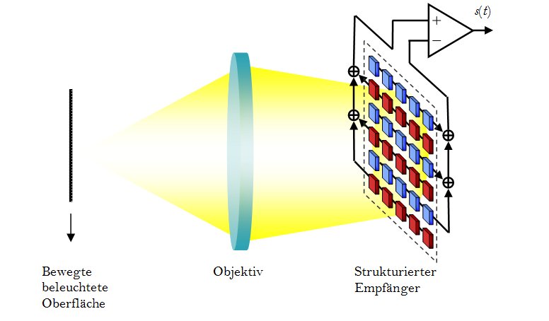
The optical spatial filter velocimetry is characterized in contrast to other non-invasive measuring systems (like the laser Doppler anemometry or the particle image velocimetry) by its simple design and the relatively low-prized system components. To measure the velocity, length, and position of objects the light that is scattered back by the inhomogeneity of the surface is superposed by an optical grating [1]. The spectrum of the original signal contains information on the velocity distribution. The filter effect of the grating and the thereby accomplished pre-processing achieves a high dynamic range. Furthermore, this technique can be used for measuring the velocity and size of spherical particles.
At the Institute of General Electrical Engineering at the University of Rostock, the optical spatial filter technique has been used for years and has been further developed using optical CCD and CMOS-array sensors [2], [3]. By weighting of individual pixels, or pixel lines, a very accurate virtual grid is generated (cf. fig. 1). Due to the investigation of the spectral distribution of spatial filter signals and statistic calculations of structure size distributions, new potential applications can be revealed, e.g. in flow measurement technology and in the analysis of object surfaces.
[1] Y. Aizu and T. Asakura, "Principles and development of spatial filtering velocimetry," Applied Physics B: Lasers and Optics, vol. V43, pp. 209-224, 1987.
[2] K. C. Michel, O. F. Fiedler, A. Richter, K. Christofori, and S. Bergeler, "A novel spatial filtering velocimeter based on a photodetector array," Instrumentation and Measurement, IEEE Transactions on, vol. 47, pp. 299-303, 1998.
[3] S. Bergeler and H. Krambeer, "Novel optical spatial filtering methods based on two-dimensional photodetector arrays," Measurement Science and Technology, vol. 15, pp. 1309-1315, 2004.
Low-cost sensors for optical velocity and position determination
When optically determining the velocity of surfaces, particle-loaded flows and piece goods in production, Laser-Doppler technique, spatial filter measuring technique as well as correlation (in conjunction with single receivers or Array sensors) are employed. In the future, the trend is towards cost-efficient and miniaturized solutions for non-contact optical determination of position, velocity, and acceleration.
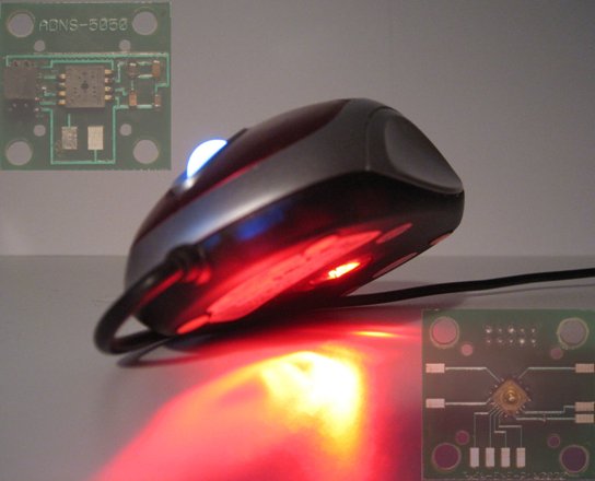
Especially in the development of PC mouse sensors, the development is highly promoted, focusing on position determination. The potential of these sensors to be used for the online determination of object velocity is explored. Fig. 2 shows two commercially used mouse sensors. The ADNS-5050 (AvagoTechnologies 2008) determines the offset between the recorded images of the 19x19 big pixel array and provides the changes in the form of increments. Another sensor is the laser Doppler sensor PLN2020 (Philips 2006), which enables measurements even on finest surface structures.