Optical measurement techniques at full scale
The propeller design process is influenced by a strong demand to reduce vibrations and underwater noise while improving propulsion efficiency at the same time. Therefore, an accurate cavitation prediction is mandatory, which is based on a precise prognosis of the full-scale wake field.
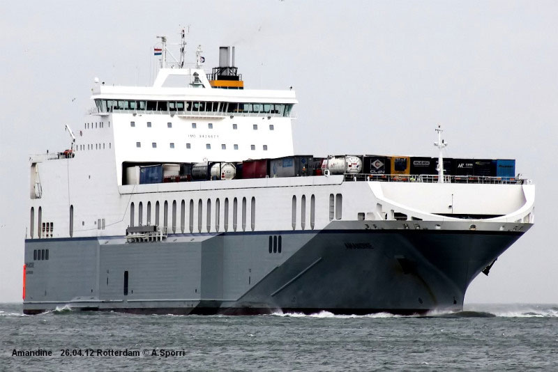
Due to the enormous experimental effort of full-scale measurements, current calculation and prognosis algorithms are not validated sufficiently with real data sets. Against this background, Particle Imaging Velocimetry (PIV) was used in the joint research and development project KonKav II to determine a full-scale wake flow for the first time. The noninvasive technique delivered reliable velocity data sets for the RoRo Ship “Amandine” (figure 1).
The comparison with CFD calculations revealed interesting insights about the width of the wake peak and indicated simulation as well as measurement accuracies. The results can contribute to better cavitation prediction algorithms.
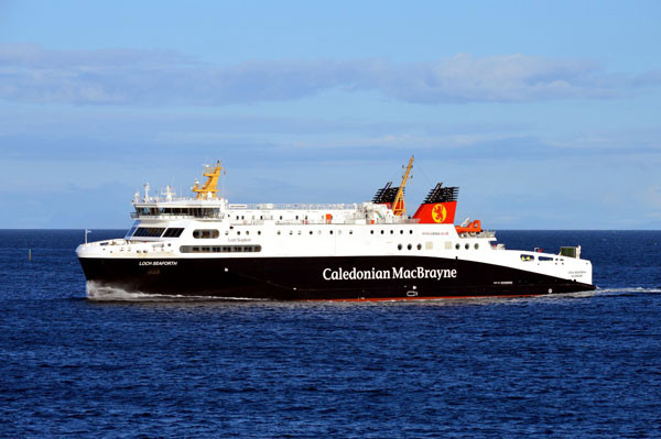
The currently running project Hykops is dedicated to streamline the propeller design process especially for innovative propulsion elements based on the development of a unique data format. To indicate the indeed increase of efficiency, the calculations should base on exact wake field velocities. The PIV measurement system is therefore applied again after an optimization process in terms of robustness, easier assembly and the ability to record 0D3C velocity data. An almost nominal wake field shall be measured on the passenger ship “Loch Seaforth” (figure 2).
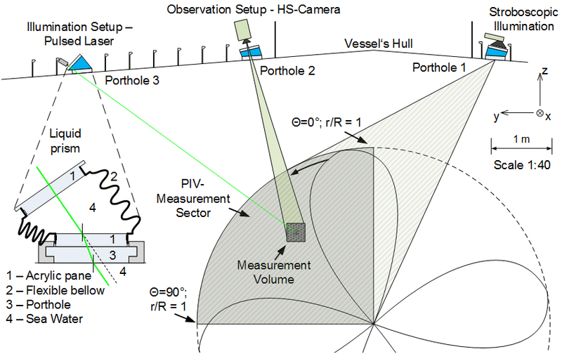
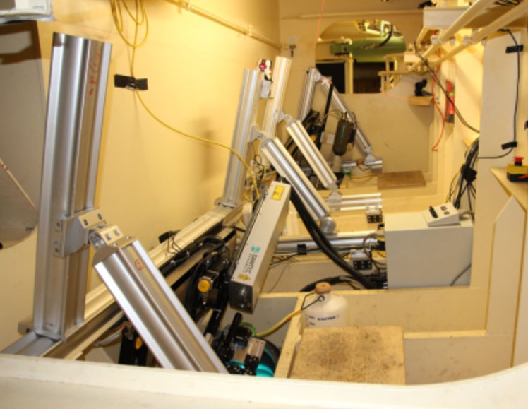
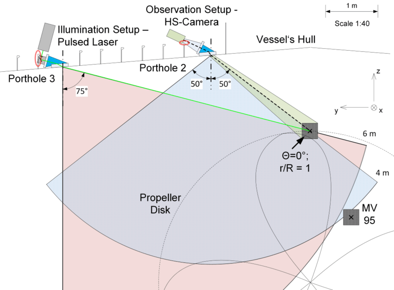
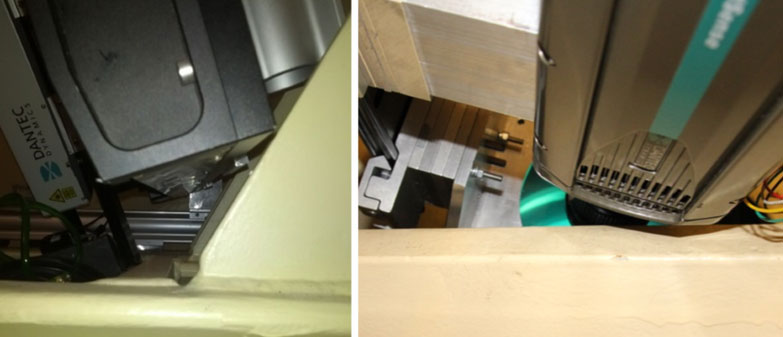
The PIV measurement principle (figure 3) is based on a double illumination and imaging of the flow at defined time intervals. The subsequent velocity calculation is based on a correlation estimation of the captured particle structures. In order to characterize the entire measuring area spatially resolved, both the observation and illumination setup must be pivoted. When the portholes are arranged almost in the propeller plane, as it was on Amandine, the measurement system can be rotated about the y-axis too in order to measure the flow velocities in front of the propeller. Precise and vibration-resistant motorized linear and rotation stages mounted on an X95-profile system (figure 4) are used for an automatic definition of each single measurement volume. The alignment of the complete setup is accomplished by a cross line leveling instrument.
Compared with previously executed LaserDoppler-measurements the PIV-measurement system convinces with the following advantages:
- Capable to record 0D2C-PIV data: In Hykops the measurement system will be evolved for 0D3C – PIV
- Rugged system against vibrations, grease and high humidity due to a relatively uncomplicated modular and encapsulated setup
- Large angular measuring range at nearly constant recording conditions
- Smaller measurement installation and data analysis effort
- High statistical confidence because of a higher data rate (350 velocity samples per second in a distance of 3.5 m), leading additionally to shorter measurement times
- No restrictions concerning the ship velocity range
- Vibrations onboard are negligible when the interfering frequencies are ten times lower than the frequency used for image acquisition (~ 714 Hz)
- Parallel recording of vibrations and ship movement (roll, pitch) to correlate the velocity measurements
- Validated measurement system: reference measurements have been executed in the towing tank of SVA (relative systematic velocity error is below ∆u/u = 5%)
- Calibration of positioning the system over a mark on the stern tube (on Amandine a mounting hole for the rope guard was used) resulting positioning inaccuracy is between 1 and 3 cm, depending on the distance
- Repeatability of positioning below 2 mm in a distance of 4 m (mainly determined by the bidirectional repeatability of the rotation axis): possibility of separate recording of calibration and velocity videos or the repositioning for single spots
- Shaft triggered and synchronized measurements (FPGA) for phase-resolved velocity data with a delay of one propeller revolution; highly needed to identify the propeller induced velocities
The most urgent requirement is good visibility in sea water with a sufficient amount of particles. Furthermore two portholes are at least necessary to observe the wake field (figure 5 and 6). A calibration mark near the stern tube is mandatory for position calibration.
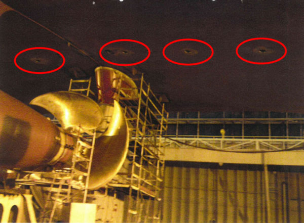
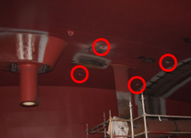
Most important is the choice of the porthole positions, since the surroundings should allow for wide tilting angles (figure 7). At “Amandine” the unfavourable frame construction (figure 8) prevented the observation of the most interesting area around θ = 0°; r/R = 1.
The assurance of approximately constant flow, weather and propulsion parameters is mandatory to correlate the measured data with simulations.
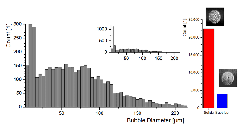
Due to its robustness and a setup similar to the PIV-technique, IPI (Interferometric Particle Imaging) was chosen to investigate the particle spectrum in terms of nuclei count and concentration, size distribution and classification. Figure 9 for instance visualizes the particle distribution in solid and spherical particles below the freight ferry “Amandine” on the passage from Rotterdam to Dublin. The number of solid particles is about 14 times higher than the amount of spherical particles.
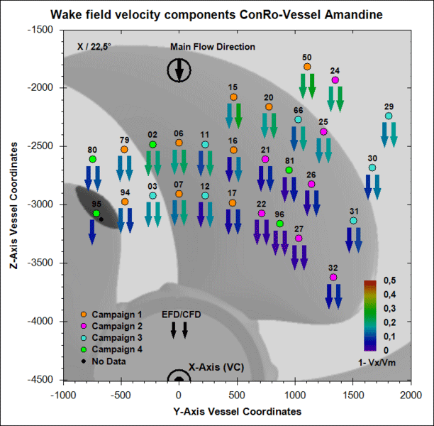
Figure 10 shows the calculated (CFD) and measured (EFD) velocity distribution in front of the propeller measured with the adapted PIV-technique.
With PIV and IPI for wake characterization and a parallel phase resolved propeller observation at full scale measurement data can be provided to evaluate the cavitation prognosis.
Related Publications:
Andre Kleinwächter, Katrin Hellwig-Rieck, Hans-Jürgen Heinke, Nils A. Damaschke. 2016 Full-Scale Total Wake Field PIV-Measurements in Comparison with ANSYS CFD Calculations – a Contribution to a better Propeller Design Process. Marine Science and Technologies
Kleinwächter A., Ebert E., Kostbade R., Hellwig-Rieck K., Heinke H.-J., and Damaschke N. 2015. PIV as a Novel Full-Scale Measurement Technique in Cavitation Research. 3rd International Symposium on Marine Propulsors Austin, Texas
Ebert E., Damaschke N., Kröger W., and Domke K. 2014a. Particle characterization system for industrial and naval applications. 8th International Conference on Sensing Technology (ICST2014).
Ebert E., Kleinwächter A., Kostbade R., and Damaschke N. 2014b. Interferometric Particle Imaging for cavitation nuclei characterization in cavitation tunnels and in the wake flow. 17th International Symposium on Applications of Laser Techniques to Fluid Mechanics.
Ebert E., Kröger W., Domke K., and Damaschke N. 2014c. Interferometic Particle Imaging system for industrial and naval applications, p. 1679-1682. SENSORS, 2014 IEEE.
Kleinwächter A., Ebert E., Kostbade R., Hellwig-Rieck K., Heinke H.-J., and Damaschke N. 2014. Full-Scale Total Wake Field PIV-Measurements for an Enhanced Cavitation Prediction. 17th International Symposium on Applications of Laser Techniques to Fluid Mechanics. Lisbon
Kröger W., Ebert E., Kleinwächter A., Kostbade R., and Damaschke N. 2014. Optische Messtechnik in der Kavitationsforschung im Schiffbauversuchswesen: Erfahrungen aus den Projekten KonKav I und II. 22. Fachtagung Lasermethoden in der Strömungsmesstechnik (GALA).
Research group full scale measurements
- Dr.-Ing. André Kleinwächter
- Dr.-Ing .Eric Ebert
- Dipl.-Ing. Robert Kostbade